https://www.powerandcables.com/132kv-link-boxes/
132KV LINK BOXES & BONDING LEADS FOR HIGH VOLTAGE HV CABLE SYSTEMS
PUBLISHED 20 JUN 2018

Link Boxes For High Voltage Cable Systems | HV EHV 132kV | Transmission & Distribution
uploaded by Chris Dodds - Thorne & Derrick Sales & Marketing Manager
HV LINK BOXES & BONDING LEADS
What Are Link Boxes?
Link boxes are installed on medium/high voltage power systems in conjunction with MV HV Cable Joints & Terminations incorporating a sheath break to prevent sheath circulating currents and limit induced voltage in the cable screen using bonded systems up to 132kV.
Underground cable bonding systems utilising 132kV XLPE insulated HV power cables are designed to provide cable sheath bonding to eliminate or reduce the circulating sheath currents and limit standing induced cable sheath voltages for safety reasons.
In an internal fault condition or short circuit of the high voltage power system the electricity current flows directly and safely to earth via the link box.
High voltage link boxes manufactured from corrosion resistant stainless steel (AISI 304L) are installed in association with cable joints to provide bonding of the HV cable circuit and at both circuit ends of the cable connected to the cable terminations – this product range complements our line of 132kV surge arresters with UK DNO and National Grid Approval.
LINK BOX TYPES
The standard ranges of single or 3 phase high voltage link boxes:
- Wall / Gantry / Structure Type IP66 – 3 Phase & Single Phase, Single Bonding Link Box (Cable Termination & Joint Location)
- Partial Discharge (PD) Type IP68 – 3 Phase Cross Bonding Link Box With SVL (Cable Joint Location)
- Pedestal Type IP66 – 3 Phase Earthing or Cross Bonding Link Box With SVL (Cable Termination & Joint Location)
- Underground Type IP68 – 3 Phase Cross Bonding & Single Bonding Link Box With SVL (Cable Termination & Joint Location)
- Underground Wall Type IP68 – 3 Phase & Single Phase Earthing Link Box With SVL (Cable Termination Location)
The link box is installed with cable joints and terminations to provide shield break accessibility for HV test purposes and to limit voltage build-up on the cable sheath – overvoltages on the sheath can be caused by fault currents, switching operations and lightning effects.

Multiple configurations are available – call to discuss your link box requirements up to 132kV
132KV
Single Phase & Three Phase Earthing Link Boxes
Thorne & Derrick can supply a complete range of 132kV Link Boxes in accordance with the Energy Networks Association (ENA) Engineering Recommendation C55/4 – ENA is responsible for maintaining the industry developed and published Technical Specifications (TS), Engineering Recommendations (ER) and Engineering Technical Reports (ETR).
ENA is the voice of the networks, representing the ‘wires and pipes’ transmission and distribution network operators for gas and electricity in the UK and Ireland.
The range of single phase and 3 phase High Voltage Link Boxes manufactured by EMELEC are ingress protected to IP66 or IP68 and suitable for indoor/outdoor wall mounting or underground direct burial – the internal connections/links are easily accessed and removed permitting disconnection of the individual sheaths for cable sheath fault testing.
Sheath testing is mandatory to ensure cable sheath integrity has not been compromised by cracks, cuts or snags during the cable pulling and laying installation.
A full set of Type Tests have been completed by the IPH Laboratory in Berlin including:
- Internal Power Arc 40kA/0.1 second
- Short Circuit 50kA/1.0 second
- Lightning Impulse 40(60)kVp
- DC Withstand 25kV/5 minute
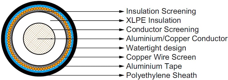
Typical 132kV Cable Construction – IEC 60840
Link Box Routine Testing
All high voltage link boxes are factory tested before shipment to customer – applied tests include visual and dimensional inspection followed by electrical tests such as AC/DC Withstand Test, Insulation Resistance Measurement Test and Contact Resistance Measurement Test.
Link boxes are available with screen bonding options including:
- Cross Bonding With SVL (Sheath Voltage Limiters)
- Direct Earthing Without SVL
- Earthing With SVL
- Single Point Bonding With SVL
Surge Arresters & Sheath Voltage Limiters
Thorne & Derrick can also supply Sheath Voltage Limiters to suit the HV cable system bonding arrangement as well as Normal Bonding Leads, Concentric Bonding Leads and High Voltage Earthing Kits for connection between the link box and the cable accessory.
SVL’s are protective devices to limit induced voltages on the bonded cable system installation due to short circuits – SVL’s are installed between the metallic screen and ground inside the link box.
The screen seperation of the power cable joints would be protected against potential damage inflicted by short circuit/break down. SVL rated voltages can be produced in accordance with client specification and the bonding system design requirements.

Bonding Cable Leads – Single v Concentric Leads
BONDING LEADS
Single Core Bonding Leads | Concentric Bonding Leads
An integral component of a Specially Bonded System is the use of bonding leads with the correct physical and electrical properties for high voltage power cable system earthing – 120sqmm, 240sqmm, 300sqmm and 500sqmm single core and concentric type leads are available for use with 132kV link box installations in buried or gantry mounted applications.
The bonding system is critical for improving and stabilising current carrying capacity of the power system – Engineering Recommendation C55/4 describes in detail the cable specification, system design and installation for HV bonding leads.
Thorne & Derrick supply both normal and concentric bonding leads with conductor sizes from 120sqmm-500sqmm compliant with the physical and electrical specification established in Engineering Recommendation C55/4.
Fire retardant sheaths can be manufactured for tunnel or substation basement applications.
Common size bonding leads are generally available from stock.
Single Bonding of High Voltage Cables – the simplest form of special earth bonding consists in arranging for the cable sheaths of the three HV cables to be connected and bonded at one single point along the circuit length without cable joints and typically comprising shorter cable circuits. At all other points, a voltage will appear from sheath to ground that will be a maximum at the most distant point from earth bond. The high voltage cable sheaths must be adequately insulated from the ground – since there is opened sheath circuit (except through the SVL) current does not normally flow longitudinally along the cable sheaths and no sheath circulating current loss in incurred.

Single Bonding – Bonding Leads
Cross Bonding of High Voltage Cables – consists essentially in sectionalising the cable sheaths into minor sections and cross connecting them so as to approximately neutralise the total induced voltage in 3 consecutive sections as show below. Typically, the HV cables are sectionalised into 3 equal length sections and cross bonding is achieved within the link box.
Pictured: Typical layout of 132kV Joint Day design with location of link box pit and bonding cables positioned.


Cross Bonding – Bonding Leads


NATIONAL GRID TYPE REGISTRATION
The full range of EMELEC Link Boxes have completed the National Grid Type Registration process. The Registration covers wall-mounted and buried link box types, across the voltage range 132kV – 400kV and is supported by authoritative test data from the IPH GmbH high voltage laboratories.
Globally, cable manufacturers and utilities specify and install EMELEC link boxes – recognising the proven consistent quality, durability and suitability of the HV EHV link boxes.
Link boxes are a critical component in any high voltage underground cable system, either for direct earthing or through Sheath Voltage Limiters and their reliability is essential for fully efficient operation including human safety. In the event of a system fault the short circuit current goes directly to earth through the link box in a controlled manner.
Contact Thorne & Derrick with link box and bonding lead sales enquiries for National Grid, UK DNO and IDNO project requirements.

Cable Joints, Terminations & Connections | 3M | Pfisterer | Nexans Euromold


